Free Practice Questions for the Autodesk Certified Professional RVT_ELEC_01101 Exam (2026 Updated)
At Marks4sure, we are dedicated to providing IT professionals with the most accurate and reliable preparation materials for the Autodesk RVT_ELEC_01101 exam. To support your certification journey, we have made a selection of our premium 2026 Autodesk Certified Professional practice questions and answers available completely free. You can take this practice test as many times as you need. Every question includes a detailed, expertly verified explanation to ensure you fully grasp the core security concepts before test day.
An electrical designer is adding lights to a project model. The coiling grids arc located in a linked Revit model. How are these lights affected if the grid patterns move?
Refer to exhibit.
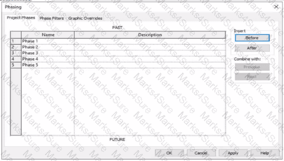
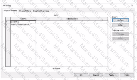
An electrical designer is working m a view set for Phase 3.
Which elements within this view will be overridden according to the " Temporary " graphic override settings?
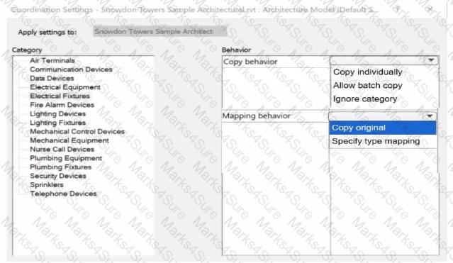
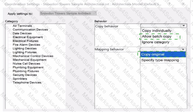
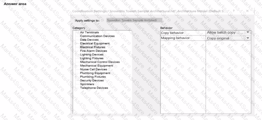
An electrical designer receives an architectural model and links it into the electrical model.
The designer wants to use the Copy/Monitor tool to copy the exact electrical fixtures created by the architect.
The designer also wants the software to automatically detect new electrical fixtures added to the architectural model.
Select the correct coordination settings from the drop-down lists
Refer to exhibit.

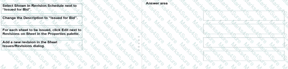
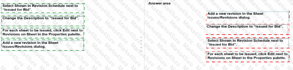
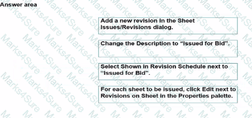
An electrical designer is issuing several sheets and wants ' Issued for Bid " to appear in the revision schedule of the title block. Drag and drop into the correct order to indicate how this can be accomplished to only the sheets that are being issued.
An electrical designer is working in a workshared project with a team of people. The electrical designer does not want to see the linked architectural model in any of their views. The rest of the team still needs to see the architectural link.
Which process should the electrical designer use?
Refer to exhibit.
(The image is presented in Imperial units: 1 In = 25 mm [Metric units rounded].)
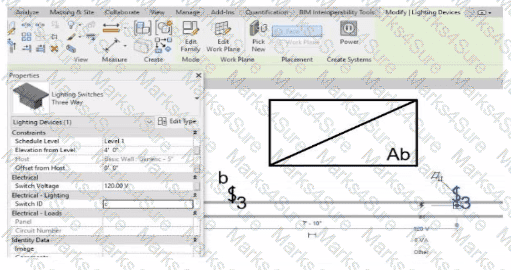
An electrical designer is trying to add the selected three-way switch to the existing switch system " b " . The designer is unable to add the switch to the switch system.
Why is this problem occurring?
An electrical designer Is working on a workshared model.
Which two worksharing display settings can the designer use to visualize model elements that have no ownership? (Select two.)
Refer to exhibits.
An electrical designer models an existing receptacle on an existing wall that the architect has indicated to be demolished.
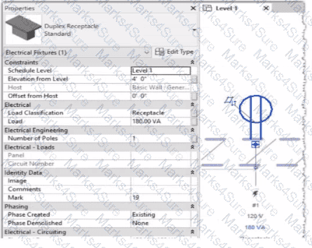
The view is intended to show demolition, and the view ' s Phase is set to New Construction. How should the designer indicate that the receptacle must also be demolished?
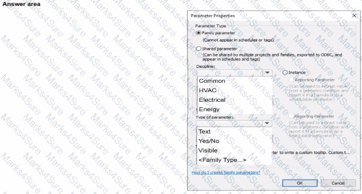
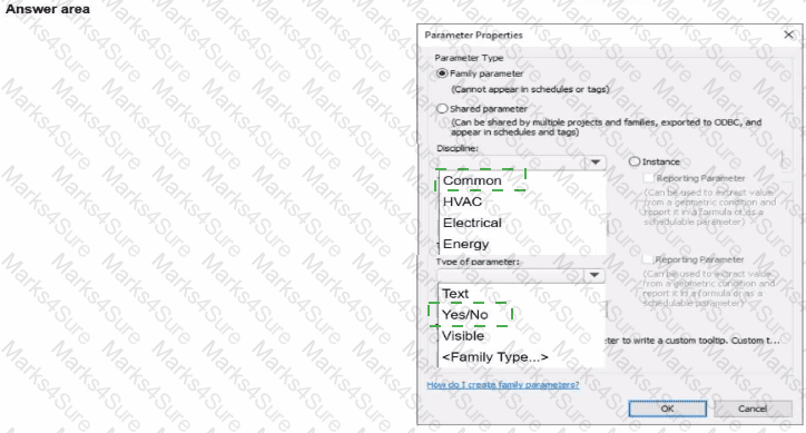
An electrical designer is creating a panelboard family. The electrical designer wants to create a family parameter to control the visibility of a clearance zone. In the Parameter Properties dialog, select the required Discipline and Type for the parameter.
An electrical designer is creating an electrical fixture family for a receptacle. The designer nests a generic annotation family that contains the receptacle symbol and a label What must be done in the electrical fixture family so that the label value can be changed in a project?
Refer to exhibit.
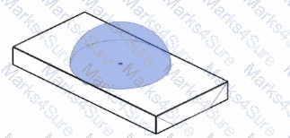
The exhibit is a lighting fixture family in the Family Editor environment and the light source is selected.
An electrical designer has downloaded a photometric web tile in IES format from a manufacturer ' s website for use within this lighting fixture family.
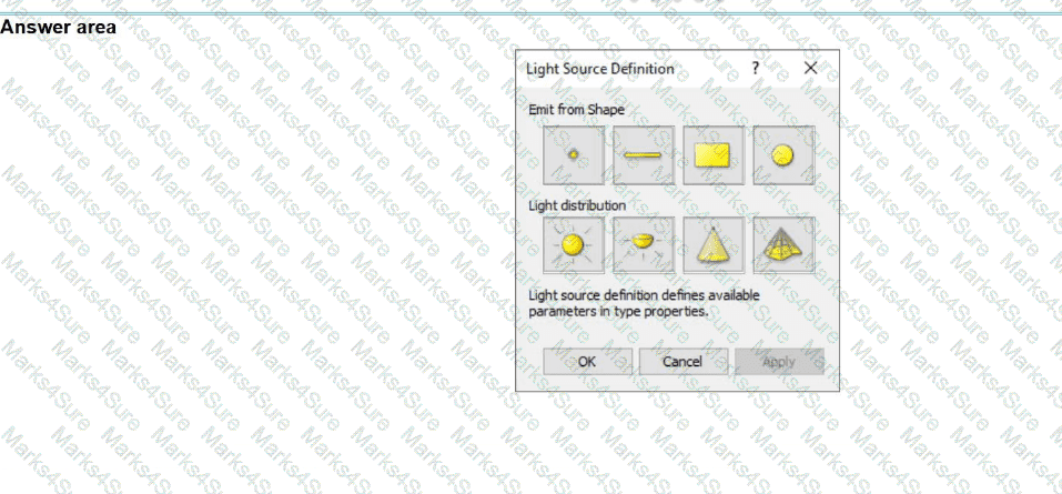
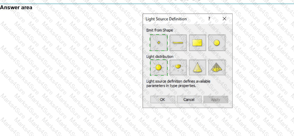
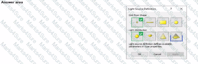
Define the light source ' s Emit Shape and Light Distribution for use with the photometric web (IES) file. (Select two in the answer area.)
Elements are added to a design option. The electrical designer needs an additional design option in the option set. All of the same elements are needed in both design options Which two methods will duplicate the element for the new design option? (Select two.)
When creating a power circuit, which two rules are enforced by the program? (Select two.)
PDF + Testing Engine

Testing Engine
PDF (Q&A)